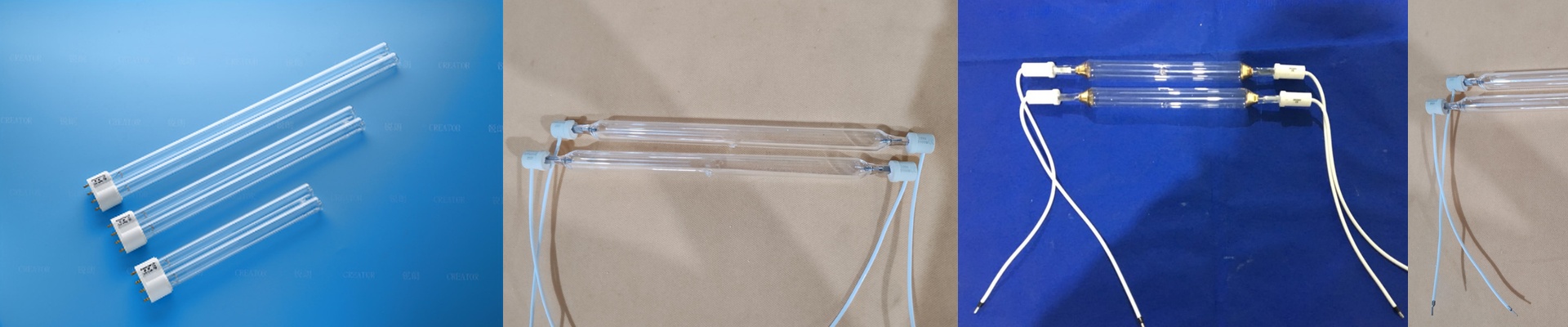
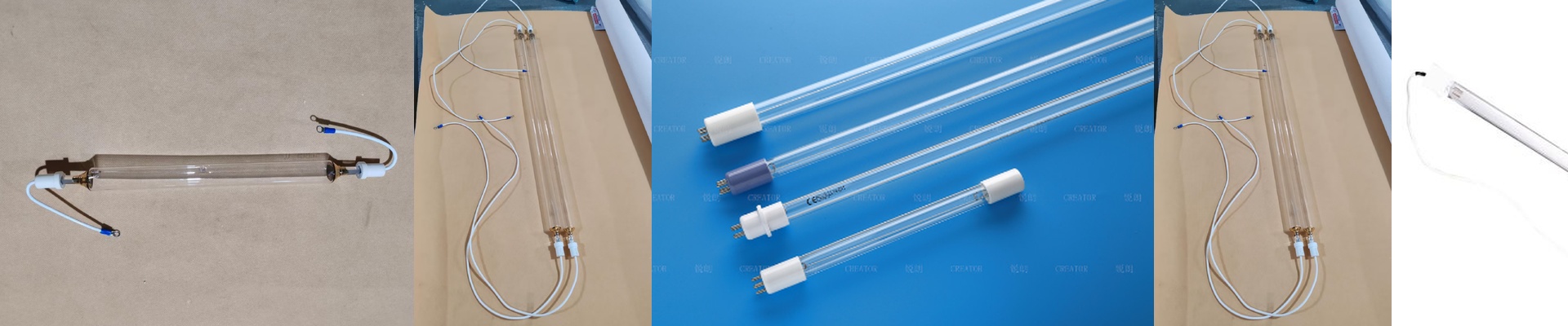
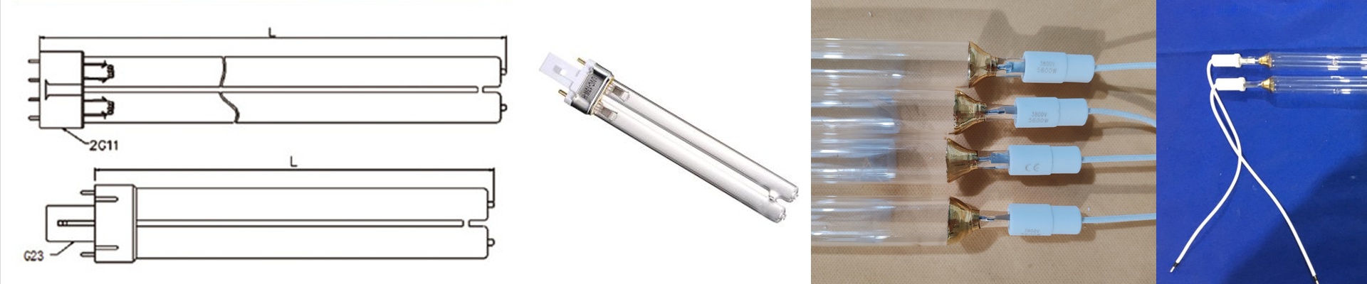
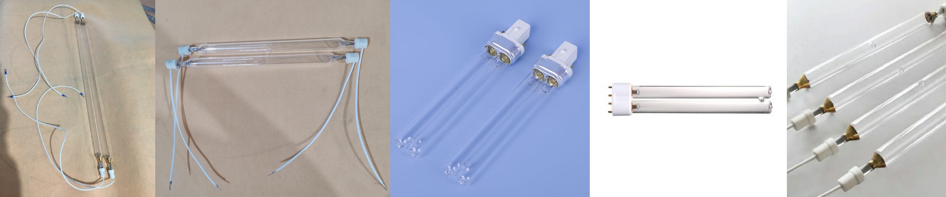
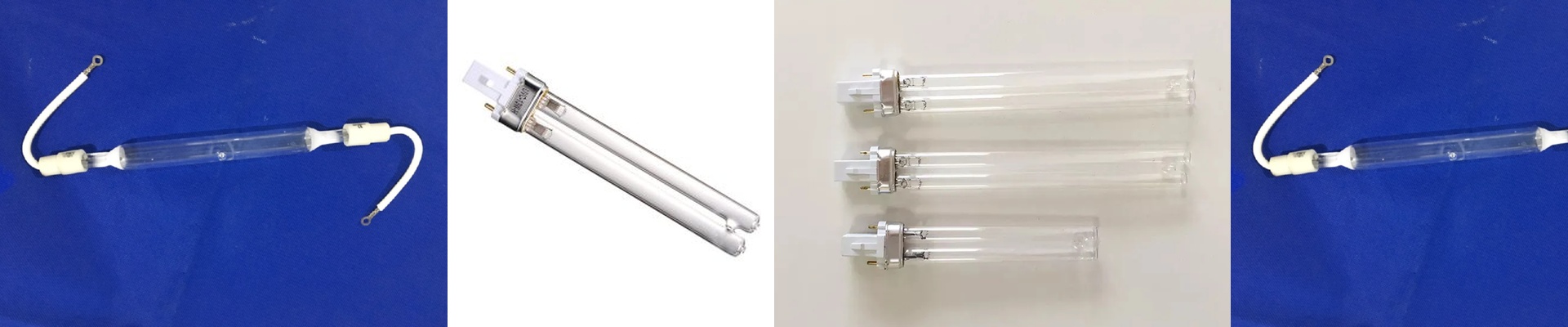
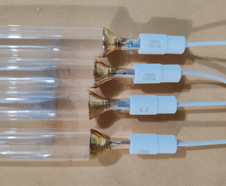
Out on the press floor, uneven UV output quietly murders throughput and quality. When the spectral profile drifts, the photoinitiators in UV offset, flexo, and screen inks don’t get the kick they need. You’re left with residual tack, adhesion that falls apart, and a pile of rejects instead of uptime. Nine times out of ten, the problem starts at the ballast. We built our UV lamp electronic ballast to hold the lamp at the exact operating point it needs, so emission stays stable and repeatable. You can set the spectrum you want, not roll the dice and hope. What actually matters under the hood UV curing is chemistry, and photons drive it. So the ballast has to deliver stable lamp current and consistent ignition, every time. With mercury vapor lamps, that means repeatable power delivery, predictable electrode temperature, and controlled spectral output. You need stable operation at the usual wavelengths—365nm, 385nm, and 405nm—with tight control of peak irradiance. In practice, that translates to consistent curing energy density (mJ/cm²) from run to run. Our ballast holds tight current regulation, keeping lamp output steady and preventing the intensity drop that shows up as slow cure, ink tack, and press stoppages. Why this holds up in real production Spectral customization starts with the lamp, but the ballast enforces it. When you need emphasis in UVA/UVB/UVC, the fill gas and quartz formulation set the emission lines—then the ballast keeps the discharge stable across the required power density. That stability matters when the press is running high speed. A stable lamp means stable curing speed, fewer micro-wrinkles, and cross-linking that stays consistent. You get repeatable results at the same press speed, instead of chasing intensity drift by constantly trimming speed up and down. Power use stays in line, too, because the ballast matches power to the lamp rather than overdriving it and dumping extra heat and ozone load into the line. The details you can’t skip Match the ballast to the lamp type, length, and arc gap. A mismatch will give you unstable ignition, premature electrode wear, and intensity loss. Check connector compatibility and mounting clearances. Airflow and spacing aren’t optional—they directly impact thermal management and long-term stability. Plan for proper grounding and EMI suppression, especially around PLCs and sensors. And remember, output is sensitive to reflector condition and alignment. Keep reflectors clean and spaced correctly, or you won’t hit the target peak irradiance at the substrate.