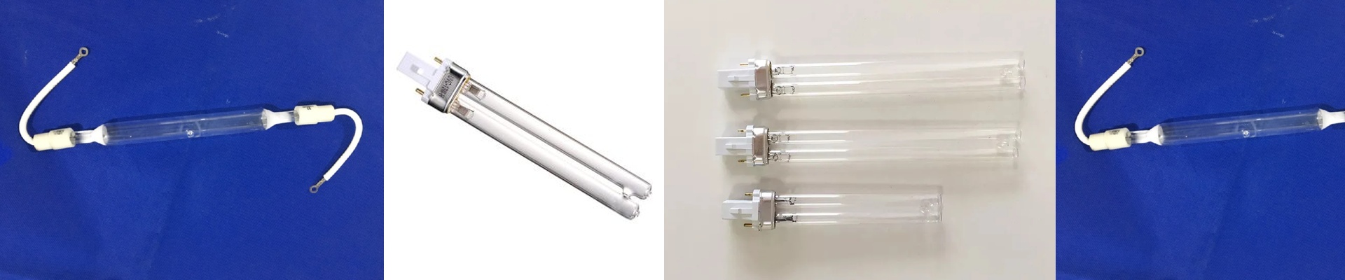
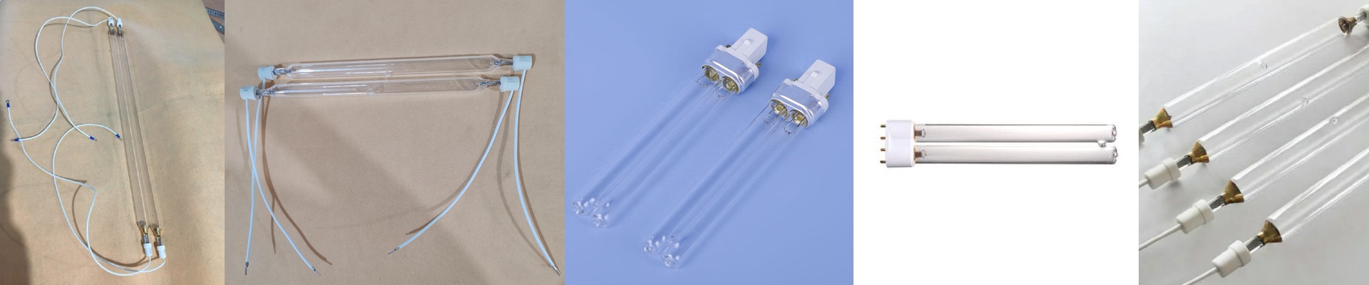
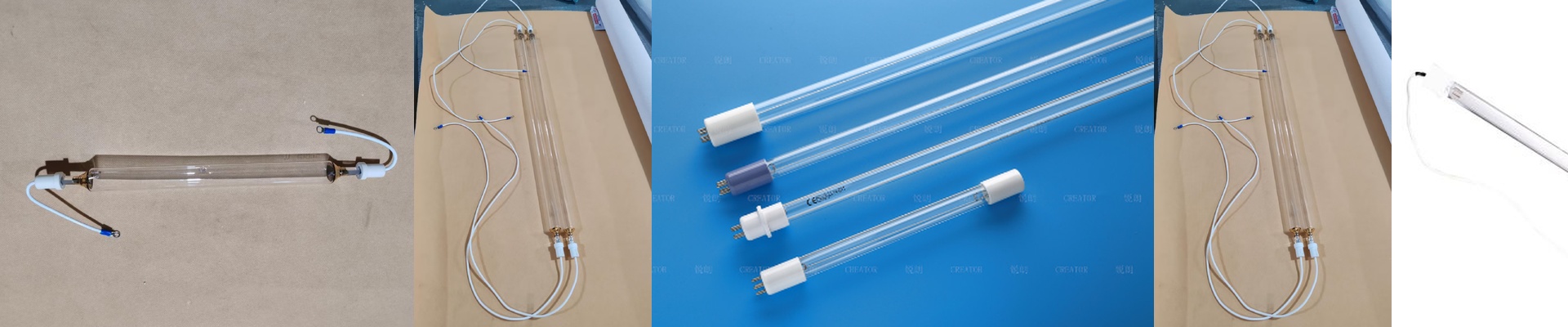
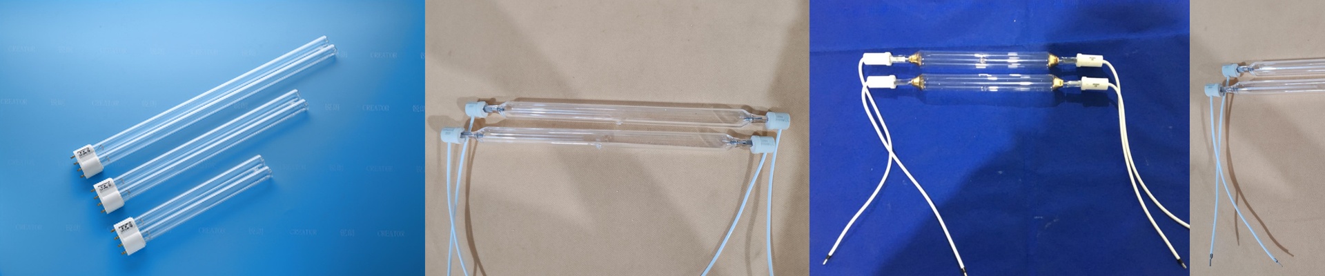
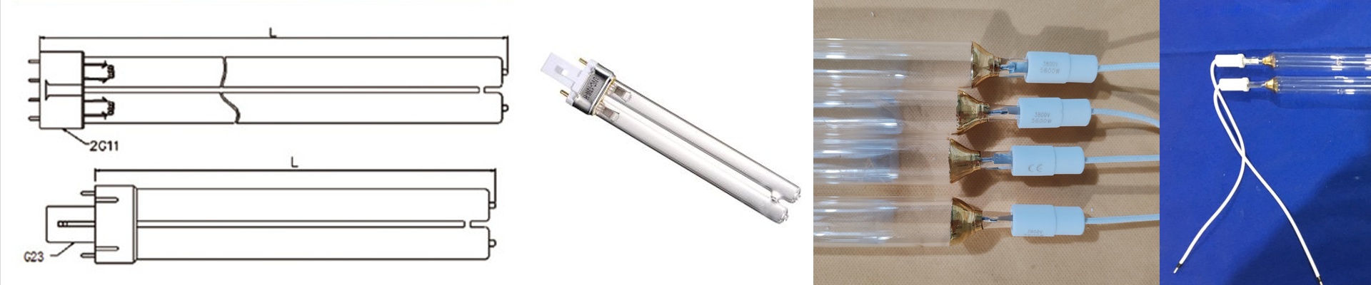
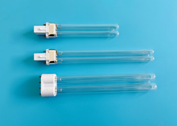
Out on the floor, the press is running. You hear the lamp fire, the shutter pop open, and the web takes off. If the lamp’s electrical signature doesn’t line up with the press’s power curve, you don’t just end up with “less power.” You get a spectrum that’s off, peak irradiance that wobbles, and ink that’s under-cured at the edges of the cure window. On the bright side, you don’t have to guess what that looks like—adhesion failure, solvent carryover, and scrap that only shows up after the ink is already down. Customization isn’t just about bolting the lamp into the space. It’s about matching the UV system to the press’s electrical behavior so the lamp behaves predictably across the entire operating range.
What actually matters, technically
When you’re talking UV through quartz, you’re really talking spectral engineering. The quartz envelope decides how much of the lamp’s UV actually gets out—and how much gets turned into heat. For industrial mercury vapor lamps, the output stacks up around 365 nm, with additional lines at 254 nm, 313 nm, and 404 nm. The ink’s photoinitiator is chosen to bite into a specific band, and the quartz transmittance envelope has to preserve that band while keeping heat under control. We talk about quartz transmittance as a curve, not a catchphrase. A high-purity quartz envelope, with controlled doping and the right coating stack, can deliver >90% transmission across the 250–450 nm range—depending on grade and how the reflector is integrated. The practical payoff is higher effective irradiance at the substrate for the same input power, because less UV is absorbed in the envelope and re-radiated as useless infrared. Electrical matching is the other half—and it’s not optional. UV lamps aren’t resistive loads. Their impedance shifts with temperature, arc length, and gas pressure. A lamp that behaves at 100% power on one machine can arc unpredictably at 60% on another. We set internal voltage and electrode geometry so the lamp’s operating point matches your specific ballast and power supply behavior. This isn’t a one-size-fits-all spec. It’s a defined voltage and current envelope that keeps the arc stable across the full dimming range, so peak irradiance doesn’t collapse when you slow the line or run thinner substrates. When you measure curing, you’re measuring energy density at the surface. That means tracking mJ/cm² across the web width, not just “lamp power.” The lamp, reflector, and power delivery have to be tuned so the delivered dose is repeatable, with a flat profile across the cure zone.
Why this works in the real world
In industrial UV printing, the press sets the power curve—and the lamp has to follow. Under-drive the lamp relative to what the press can deliver, and the arc starts to flicker, warm-up behavior gets inconsistent, and spectral output drifts during the run. Over-drive it, and you get excess heat, faster electrode erosion, and lamp life that falls off—often showing up as a sharp drop in irradiance after a few hundred hours. We build the lamp around your press’s electrical behavior. That means specifying internal voltage, electrode gap, and fill pressure so the lamp ignites reliably, runs stable, and holds output across the dimming range. Pair that with quartz transmittance tuned to the mercury spectrum, and you get more usable UV at the substrate and less heat load on both the substrate and the chill rolls. The operational payoff is straightforward. With a matched lamp, you run at the intended speed without chasing cure failures. Adhesion improves because the photoinitiator gets the dose it was designed for, and cross-linking happens without solvent retention. Energy use drops because you’re making more curing photons per watt, and lamp changes come less often because the lamp stays within its designed electrical envelope. Cure consistency holds up across formats, too. Whether you’re running narrow labels or wide packaging, the lamp’s output profile stays stable when the electrical interface is matched to the machine.
A few things to keep in mind
A matched electrical interface only works when the whole UV system is aligned. Reflector geometry, dichroic coating selection, and shutter timing all shape the delivered dose. If the reflector is mismatched to the lamp, the spectral gains from high quartz transmittance get lost in poor focus and wasted energy. Installation needs coordination. The lamp’s internal voltage setting isn’t something you dial in on the fly—it’s set at manufacture based on your machine’s power curve, arc length, and operating range. Give us the press model, ballast type, dimming range, and target irradiance at the substrate. We’ll specify the lamp to meet that curve, including connector type, envelope dimensions, and mounting constraints. One practical constraint: boosting transmittance in the UV bands raises output, but it also raises heat at the envelope surface. Make sure cooling airflow, lamp housing clearance, and substrate heat tolerance are adequate. In tight spaces, the lamp may need a slightly lower power setting to keep substrate temperature within limits. That’s a normal trade-off to protect both the lamp and the printed product. If you want the lamp to perform the way it was designed, start by telling us the machine. Then we can match the lamp to the power curve—and the quartz transmittance to the cure chemistry.